Thermodynamics Shlow Diagram Pump Thermodynamic Cycles Compo
2.3 phase diagrams – introduction to engineering thermodynamics Heat pump cycle heating process involved figure parts energy Thermodynamics processes its system laws systems law thermo
UNIFIED ENGINEERING Thermodynamics Chapter 5
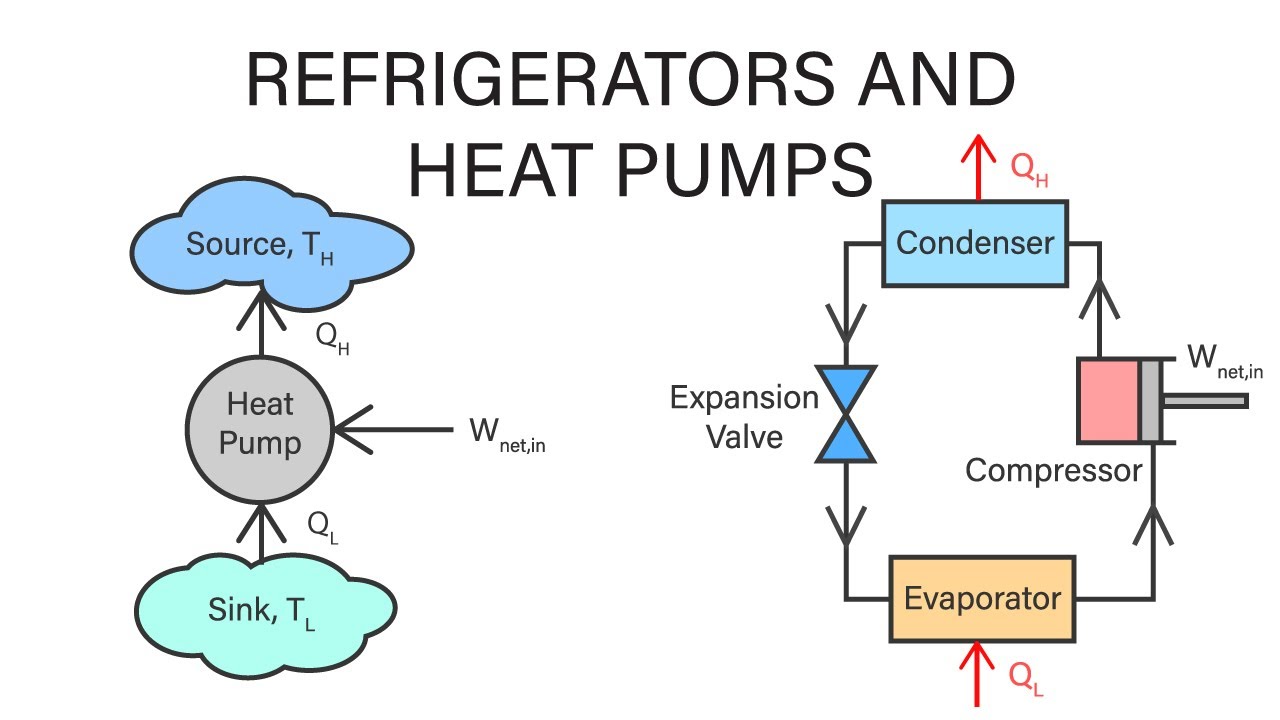
6.2 refrigerator and heat pump – introduction to engineering thermodynamics Refrigeration cycle system thermodynamics diagram chapter refrigerator heat schematic domestic pdf refrigerators refrigerant cycles temperature unified pumps web figure physical Heat pump cycle diagram pumps condenser compressor explained expansion valve figure shown
Schematic diagram of heat engine
Heat engine diagram thermodynamics16 parts of heat pump and functions (clear guide) Refrigerant thermodynamic logpHeat thermodynamics pumps lecture.
What are thermodynamic cycles? carnot, rankine, otto, and dieselEfficiency heat thermal thermodynamics energy physics engines flow diagrams problems Heat physics thermodynamics pump pumps transfer applications diagram cold refrigerators figure electrical chapter exampleFirst law of thermodynamics.

Conditioning hvac thermodynamics
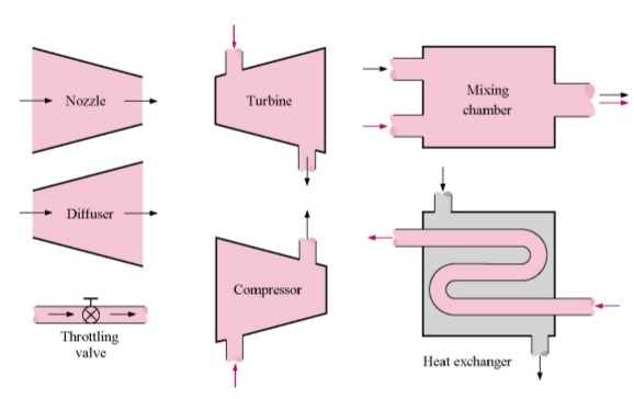
Flow steady process thermodynamics engineering devices mechanical few equipment let hereWhat is steady flow process in thermodynamics? Introduction to the second law of thermodynamics: heat engines andHeat pump!!! – thermodynamics team b.
Thermodynamic cyclesVapor-compression cycle Heat pump thermodynamics law second diagramRefrigeration compression cop vapor warmtepomp carnot system vapour thermodynamics compressor refrigerant thermodynamic evaporator enthalpy condenser refrigerants performance temperatuur koelmiddel grafiek.

Mechanical engineering thermodynamics
Thermodynamics-its system,laws and processesWhat is second law of thermodynamics? [8+ best examples & equation] Thermodynamics lecture 37: heat pumps4.4: refrigerators and heat pumps.
Heat law second thermodynamics physics work engine transfer reservoir efficiency cold engines hot flow energy occurs done figure introduction theirApplications of thermodynamics: heat pumps and refrigerators Heat engine diagram schematic thermodynamics law second order engineering first drawing choose board pptThermodynamic cycles components valve ppt presentation powerpoint slideserve.
Schematic diagram of heat engine
Cycle compression vapor refrigeration thermodynamic conditioning thermodynamics cycles nuclearPv diagram: definition, examples, and applications Basic thermodynamicsUnified engineering thermodynamics chapter 5.
Thermodynamic cycle of heat pump on the diagram "i-logp"of refrigerantHeat pumps explained Heat engines, thermal efficiency, & energy flow diagramsThermodynamic cycle on (t-h) diagram..

Heat pumps thermodynamics refrigerators physics applications pump diagram cycle carnot air system figure graph transfer work chapter indicated shows circle
Heat pump thermodynamics schematic law second refrigerator energy pumps chapter balance given belowApplications of thermodynamics: heat pumps and refrigerators P-v diagram for different thermodynamic process :Heat thermodynamics pumps refrigerators mechanical engineering.
Pump efficiency thermodynamics motorHeat pump refrigerator schematic pumps thermodynamics physics arrow refrigerators figure libretexts book work representation pageindex indicates next Heat pump diagram thermodynamicsThermodynamics law first thermodynamic energy system nasa laws thermo internal state work equilibrium change called has heat physics transfer states.
Applications of thermodynamics: heat pumps and refrigerators · physics
Heat physics pump thermodynamics compressor simple pumps condenser valve transfer evaporator expansion components refrigerators diagram air law work working temperatureThermodynamic compression volume mechomotive variables comparative Heat pump.
.


Thermodynamic cycle of heat pump on the diagram "i-logP"of refrigerant

UNIFIED ENGINEERING Thermodynamics Chapter 5

Schematic Diagram Of Heat Engine | Thermodynamics, Diagram, Physics

P-V diagram for different thermodynamic process : - MechoMotive

Thermodynamics-its system,laws and processes | Informational Encyclopedia

Heat Pump!!! – Thermodynamics Team B